FAQs & Top Tech Issues

Fast, Reliable Answers for Need-To-Know Questions

Who has time for a phone call or email nowadays? Here is a selection of top technical questions asked by SonTek customers. We will continue to build on this list, so check back on a regular basis. Of course, we always welcome hearing from you, so if your question is not listed here and you need help, contact Technical Support or call +1.858.546.8327.


SonTek-SL: Using beam velocity data for QA/QC

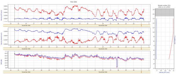
The individual beam velocities should mirror each other (Figure 1) if the measurement site and installation complies with the specified requirements. It is expected that the beam velocities will not mirror each other exactly and it is acceptable if there are small variations between the two beams.

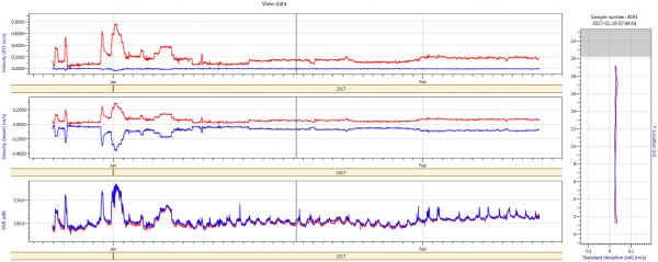
When using the beam velocities to analyze the data it is recommended that the data is evaluated over an extended period to identify a change in the data trend between the two beams. Evaluating a short period (couple of days) could be misleading. There are number of factors that can result in a difference between the beam velocities (Figure 2),

a) Vegetation or debris impacting the measurement volume of one of the beams,
b) Sediment deposition or sand bars moving downs stream that is impacting the measurement volume,
c) Algae or Biological growth on one of the transducers,
d) One beam interacting with water surface or channel bed
e) Fish presence in measurement volume.

It is important to note that Beam Velocities should not be used independently to review the data quality and that it should be used in conjunction with Standard Deviation of Velocity, Stage (Vertical Beam \ Pressure Sensor) versus Flow and BeamChecks data.

sl3g-beam-velocity-qa-qc-1.png

sl3g-beam-velocity-qa-qc-2.png

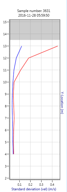
SL3G Standard Deviation of Velocity QA\QC

The standard deviation of the velocity between the two beams should be similar (Figure 1) for the entire profile if the measurement site and installation complies with the specified requirements. It is expected that there will be small variations in standard deviation between the two beams.

When using standard deviation of velocity to analyze data it is recommended that the data is evaluated over extended period to identify a change in the data trend between the two beams. There are number of factors that can result in a difference between the beam velocities (Figure 2),

a) Vegetation or debris impacting the cells located at the far end of the measurement volume,
b) Sediment deposition or sand bars moving downs stream that is impacting the cells located at the far end of the measurement volume,
c) One beam interacting with water surface or channel bed that is impacting the cells located at the far end of the measurement volume,
d) Fish presence in measurement volume.

It is important to note that Standard Deviation of Velocity should not be used independently to review the data quality and that it should be used in conjunction with Beam Velocities, Stage (Vertical Beam \ Pressure Sensor) versus Flow and BeamChecks data.

sl3g-standard-deviation-of-velocity-qa-qc-1.pngsl3g-standard-deviation-of-velocity-qa-qc-2.png

What is the proper way to mount my Sontek-IQ instrument?

The installation process of SonTek IQ instrument is important component to ensure that the instrument operation and hardware components are not affected. The following basic steps should be followed during the installation of the instrument:

a) Depending on the application, the mounting fixtures available to secure the instrument consist of Mounting Brackets, Riser Mount and Pipe Ring,

b) The mounting holes provided on the side of the instrument should be used to fasten the instrument to the mounting fixtures. Users should NOT use the bottom plate of the instrument to secure against a mounting plate,

c) Secure the power and communication cable to the bottom and side of the channel. Protect the cable by routing it through a conduit,

d) If the cable needs to be bent near the IQ, keep bend radius no smaller than 4 inch (10 cm).

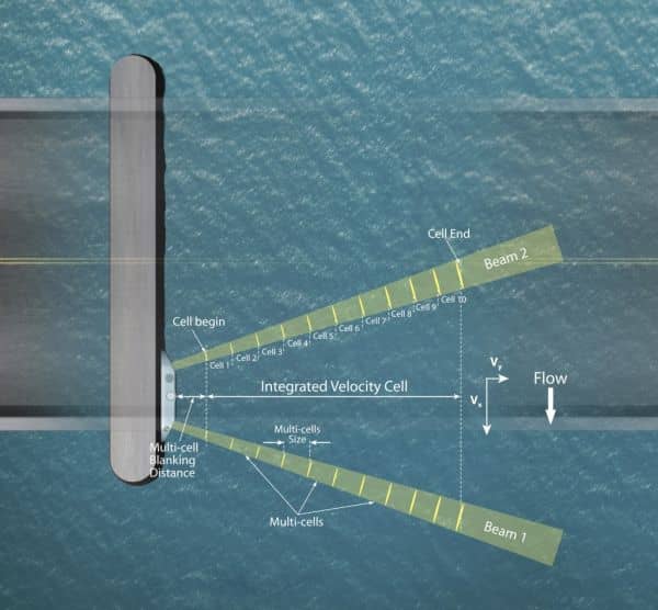
Cliffnote version of Sontek-SL 3G measurement principles

The SonTek SL3G measurement principle is based on two acoustic beams each slanted at 25° off the instrument axis. The system measures velocity in a horizontal profile that is dived into multiple cells based on the user configuration. The profiling range of the SL3000 and SL1500 instruments are 0.1 to 5m and 0.2 to 20m respectively with up to 128 cells that can be incorporated along the horizontal beam based on user configuration.

The multi-cell velocity measurements are used to develop two main velocity groups,

a) "Horizontal averaged velocity" is the average X and Y velocities components of all the multi cell velocities.

b) "Average velocity in user defined cell" is the average X and Y velocities components of all the multi-cells within the Integrated Velocity Cell (IVC). The IVC has a user-defined cell begin and cell end.

The measurement of accurate and reliable data is dependent on measurement site conditions, flow conditions, instrument installation and configuration. It is important that the following aspects need to be adhered too to ensure quality data,

a) The flow at the measurement site should be homogenous, both beams exposed to the same conditions.

b) Instrument should be aligned perpendicular to the main flow direction. The Y Velocity component should be as small as possible,

c) The location of the last cell based on user configuration should not be closer than 10% of the total width from the opposite bank,

d) Aspect Ratio of 1:20 indicates the minimum distance the measurement volume should be from channel bottom or water surface.


sontek-sl-downlooking (1).jpg

What do I need to know about the RiverSurveyor compass?

Several customers have reported some cases of anomalous discharge data when using the RiverSurveyor product line with DGPS as the velocity reference. Upon investigation by our technical team and in conjunction with key customers, it was determined that there were deficiencies in the internal compass performance and some flaws in the implementation of the compass subsystem into the overall RiverSurveyor product.

To address these issues, SonTek has developed a new compass with enhanced performance that will improve the consistency of the discharge data when using DGPS as the velocity reference. This new compass has been extensively tested by SonTek. We believe this new compass will improve accuracy of M9 and S5, especially in moving bottom conditions. Customers who operate their units exclusively using bottom tracking as the velocity reference will not see any difference in their discharge results and therefore do not require any change.

This solution is now available to M9 and S5 customers using RiverSurveyor with a laptop PC. Solutions for mobile platform will be following within a couple of months. If you have questions about how this issue is affecting your results and whether or not you want the new compass, please contact your SonTek support representative. Those opting to receive a new compass must send their unit to the SonTek facility in San Diego, only after making arrangements with the SonTek Customer Service department by contacting support@sontek.com or 1-858-546-8327. Starting with orders placed on or after October 21, 2014, new M9 and S5 units from production will include the new compass as standard.

My M9/S5 won’t start a new measurement and/or fails the system test. What can I do?

As long as the batteries are new or properly charged, the next thing to do is to format the M9/S5 recorder. If communications wasn't lost during data collection, then the .riv files stored on the M9/S5 recorder will match the .rivr files saved to the computer. In that case, you don't need to download the files from the M9/S5 prior to formatting the recorder.

I cannot connect to the castaway using the Bluetooth USB radio. What can I do?

It could be due to a conflict between the laptop's internal Bluetooth and the USB radio dongle. Try the following steps:
1) Disconnect the Cirago USB dongle from the laptop

2) Go into Uninstall a Program and look for Bluetooth stacks
   a. Do NOT uninstall your internal Bluetooth stack
   b. Remove any Bluetooth Stack for Windows by Toshiba (installed from    Cirago website)
   c. Remove any other non-Microsoft Bluetooth stacks

3) Open up Device Manager
   a. You should only see your internal Bluetooth stack
   b. Insert the Cirago USB dongle and wait for Device Manager to refresh
   c. If you see a conflict or caution icon, remove the Cirago dongle from the PC
   d. Wait for Device manager to refresh and then right-click to Disable the internal Bluetooth
   e. Once refreshed again, insert the Cirago USB dongle
   f. Allow Windows to install a driver. The conflict should be resolved and the dongle should blink blue.

4) Open the CastAway software and attempt to connect

Notes:
- Do NOT pair the CastAway with any Bluetooth manager
- Do NOT install third party Bluetooth drivers/managers (e.g. Cirago, Toshiba)
- Restart the CastAway software after any Bluetooth changes

The castaway software installed without errors, but it won’t run when I double-click the icon. How can I fix this?

The software zip file should include a folder called SQLCE_35_SP2. Read the Install.txt file and run the appropriate .msi file(s). If the problem persists, run the dotNetFx35setup.exe file in the DotNetFX35 folder.

Where can I download instrument or software manuals?

Manuals are installed with the software used to operate the each instrument.  When the default installation settings are used, a link should appear in the SonTek Software folder of Programs directory.  The manuals can also be accessed from the Help menu within the software.

I can’t connect to my SonTek device. What could be wrong?

There are several possibilities, but the most common reason is the COM port connection.  Native serial ports (particularly on laptops) can be intermittent at the higher baud rates used by SonTek software to communicate and download data.  For this reason, SonTek supplies a USB to serial adapter with new instruments (http://www.easysync-ltd.com/product.php?ProductID=526).

The first thing to do with the USB adapter is to install the latest driver.  It can be downloaded as a Setup Executable from the Comments section of the table here: http://www.ftdichip.com/Drivers/D2XX.htm

Note: It may be required to reboot the PC after installing the device driver.

How do I know which com port to select in the SonTek software?

If you are using a native serial port, it is usually COM 1.  If you are using a USB to Serial adapter, navigate to the Device Manager to verify the COM port number.  The Device Manager can be found by searching from the Start menu or Control panel depending on the Windows version installed on the PC.  Open the Device Manager, expand the 'Ports (COM & LPT)' section and look for USB Serial Port.  The COM port number appears in parentheses.

Note: If you are trying to connect to your instrument using SonUtils, ViewArgonaut, FlowTracker, or HorizonADV and the COM port number is greater than 8, you will need to reassign the COM port number.  To do this, right click on the USB Serial Port and choose Properties. Under the Port Settings tab, choose Advanced and change the COM Port Number from the drop down menu.

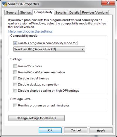
Why does SonUtils return an error message when the break button is clicked?

This can occur on some computers running Windows 7 (or higher).  It can be resolved by running SonUtils in Compatibility Mode.  First, right-click on the SonUtils icon and select Properties.  Then click on the Compatibility tab.  Check the box to "Run this program in compatibility mode for:" and select Windows XP (Service Pack 3) from the drop-down list.  If the Privilege Level box is available, check it to "Run this program as an administrator".

sonutils.jpg

My SL is reporting -1 for water level, why is this?

The Argonaut-SL has a pressure sensor that needs to be calibrated on site before deploying the instrument.  In order to calibrate the pressure sensor, first connect to the SL using SonUtils.  Send a BREAK to wake up the instrument.  Type SENSOR CONT into the command line at the bottom and press Enter. Temperature, Pressure and Battery voltage will start to output.  Press Enter again to stop data output. If your Argonaut is in air, it should read a pressure value of less than 0.1 dBar or if the unit is in the water it should read within 0.1 dBar of the depth (in meters).  If the pressure sensor shows a significant offset, you will need to reset the pressure offset. To do this type RESETPRESSOFFSET into the command line, press Enter.  If the system is in air, enter 0 when prompted.  If the system is in water, measure the distance from the water surface to the top of the vertical beam and enter this value when prompted (the units will depend on your setup). Press Enter. Type SENSOR CONT into the command line, press Enter and verify the new pressure offset by comparing the output pressure to the deployment depth.

How can I check that my Flowtracker or adv is collecting accurate velocity measurements?

Beamcheck is the best diagnostic predictor of reliable ADV velocity data.  Record Beamcheck data with the probe fully submerged in the water and the sampling volume clear of interference.  Tap water is usually sufficient for this test, however depending on how "clear" your tap water is, you may need to add a handful of seeding material (e.g. dirt, chalk dust).  In the beam check program, you can change the X-axis to samples/counts using the View menu.  The rule of thumb for accurate velocity measurements is that all beams should be within 10 counts of each other for both the Peak Position and Peak Level.  A nominal value of the peak level will depend on the amount of scattering material in the water.  You should see an increase in the peak level if you add more seeding material.  If you are uncertain of your results, please record at least 30 pings and send the .bmc file to support@sontek.com.  We will be happy to provide feedback.

How do I create a log file for review of instrument configuration?

For SonUtils 3.02 and later:  Go to the File menu and select Open Log File (Alt+L). This will bring up a 'Save As' window. Select a file name and destination and click Save. After you click Save, the name of the Log File should appear at the top of the screen. Next, connect to the system and send a Break to wake it up. Then click on each of the four "Show" icons in the left side of the window (Show Configuration, Show Setup, Show System and Show Deploy). Type the commands SENSOR, DIR and TEST individually. Finally, under the File menu, choose Close Log file. The Log File name at the top of the screen should disappear. All of the data is saved as ASCII text. Please check the text file before sending it to be sure all the data is there.

For SonUtils 2.51 and earlier:  In order to create a log file, first enter the Terminal module in SonUtils. Go to File and select Log File (Alt+L). This will bring up a 'Save As' window. After you click Save, the name of the Log File should appear at the bottom of the screen. Next, connect to the system and send a Break to wake it up. Then click on each of the four icons in the 'Show Instrument Settings' box (Conf, Setup, System and Deploy) on the left of the screen. Type the commands SENSOR, DIR and TEST individually. Finally, under the File menu, choose Log file again. The Log File box at the bottom of the screen should now read <NONE>. All of the data is saved as ASCII text. Please check the text file before sending it to be sure all the data is there.

How do I upgrade RiverSurveyor live and/or RiverSurveyor stationary live software on my mobile device?

First, download the latest RiverSurveyor software here: http://www.sontek.com/sw/riversurveyor-live.php.  Once the installation files are saved to the PC, you will need to transfer the .CAB file to your mobile device.  There are two options for transferring files: an SD card reader or connect the mobile phone to your PC using ActiveSync (XP) or Windows Mobile Device Center (Vista or later).  Once transferred, use the File Manager to open My Documents on the mobile device.  Click on the RiverSurveyor Live.CAB file to run the installation

Why do I get a C++ error message when trying to install the SonTek-IG software?

This can happen on some computers when running the .exe software installation file.  Run the .msi installation file instead.  Contact support@sontek.com if the problem persists.

How can I fix the compass initialization errors that appear in SonUtils?

The most common cause of the "ERROR: Compass not responding. Re-initializing..." message in SonUtils is the connection between the ADV/ADP probe head and the 16 pin probe cable to the processing electronics.  Check the female bulkhead connector with a flashlight for any dirt or debris that may have collected.  It can be cleaned with a cotton swab, compressed air or water.  Use some silicon grease or spray to lubricate the pins on the probe cable.  Be sure to mate the connectors completely so that the faces are touching or within 1-2 mm before screwing down the locking sleeve.  Do not use the locking sleeve to tighten the connection.