


Switch to Domestic Pump
Volume 6/ Issue 2/ August 2019
Float switches are very important part of Domestic Pump units. They perform variety of functions for both condensate return and boiler feed units. The switches are operated by the movement of the water level in the tank. They include electrical and mechanical parts. The electrical part is in a an electrical conduit box that is seen on the outside of the tank. The mechanical part includes a rod and a float – both of them are inserted into the tank and move up and down with the water level. When the float reaches the required set point it will either close or open the electrical contacts, depending upon the position of the float switch and the type of control.
Condensate return units include pumps that are controlled by the water level in the tank. When the float of the float switch reaches the preset high point, it will close the electrical contacts on the switch and power the pump. The pump will then start pumping the water out of the tank until the float drops to its low point and opens the contacts on the switch thus stopping the pump. The float controls ensure there is some water left in the tank to keep the pump primed and the float switch starts the pump before the tank overflows. Each pump may have its own dedicated float switch (photo 1), or the unit may be equipped with a duplex switch called “mechanical alternator” (photo 2). The mechanical alternator will control two pumps with a single float in the tank. This alternating device will sequence the lead-lag role of each pump thus operating the two pumps more evenly, and its single float provides space for installing more control switches in the tank.
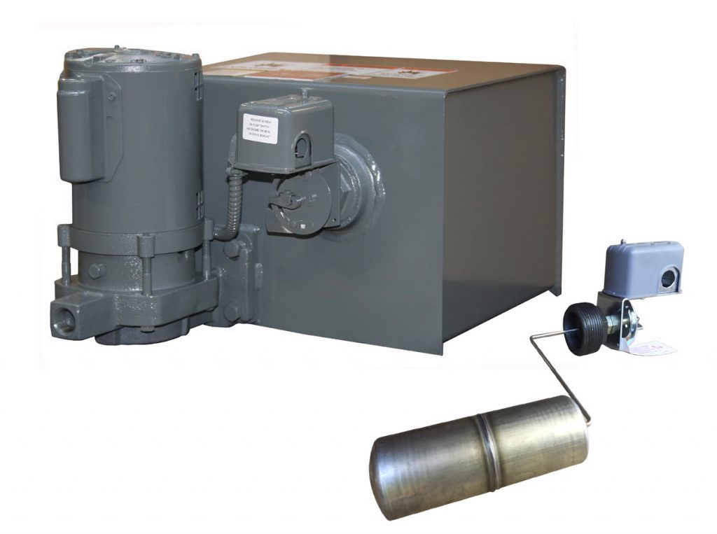
Photo 1: A float switch and a simplex unit with the float switch on.
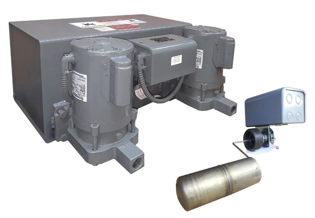
Photo 2: A mechanical alternator and a duplex unit with the mechanical alternator on.
There is a variation of the mechanical alternator that very much looks like it but its alternating function is disabled. Why? Because some customers prefer to have an electrical alternator instead, or to not have alternation at all, but include an additional float switch, say for a high level alarm. This, combined with fewer openings on a smaller tank is the reason to use the non-alternating duplex switch. Here is an example – you need to control two pumps without mechanical alternation, and you also need to have high level alarm switch, too, but the receiver tank can only accommodate two float switches. The solution to that example is to use the duplex non-alternating switch and a second switch for the high level alarm. The working principle of the high level alarm float switch is the same but its function is to send a signal to the control panel and trigger an alarm.
Speaking of alarms – what about the low water level alarm? Here, opposite to the high level switch, we would need the contacts to close when water level drops too much. We can achieve this by using a float switch with reverse action. Such a switch is also used to control a make-up water solenoid that is normally closed. The two examples for reverse-action float switch are primarily used on boiler feed units. Those units are not controlled by the water level in their own tank, but by the water level in the boiler they are feeding. That is why we use safety switches like for low level alarms, for controlling make up water connections, and for stopping the pumps in case the water gets so low that even the make-up water capacity cannot catch up with the boiler demand.
Float switches are robust, long-lasting and a simple solution for opening and closing electrical circuits. Once the user has selected the required unit features and enclosures, they do not need to worry about switch design, dimensions, materials or adjustment. Just get yourself familiar with the operating manual and remove the shipping bracket off the switches before operating the unit – all else has been covered and tested in
the factory.
Any questions? Let me know.